To study and draw the characteristics of rectifier filter circuit.
Power supply, rectifier kit, CRO, Connecting leads.
Brief Theory:The output from any rectifier is not pure dc but also has some ac components, called ripples along it. It is important to reduce ripples from the pulsating dc supply available from rectifier circuits to the minimum. This is achieved by using a filter circuit which removes the ac components and allows only dc components to reach the load. A filter circuit is a device that converts pulsating output into a steady dc level. A filter circuit is generally a combination of inductors & capacitors. The filtering action of L & C depends upon the facts that an inductor allows dc only & capacitor allows ac only to pass.
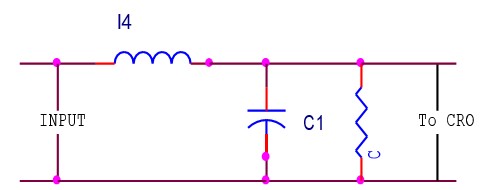
Circuit Diagram:


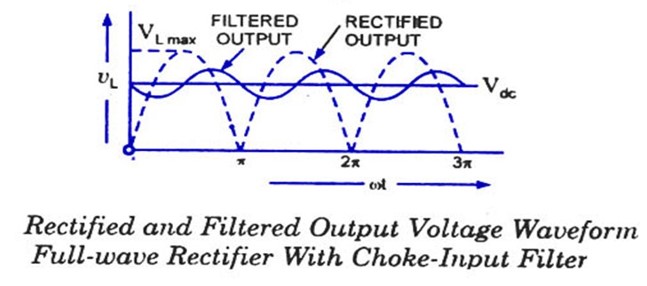
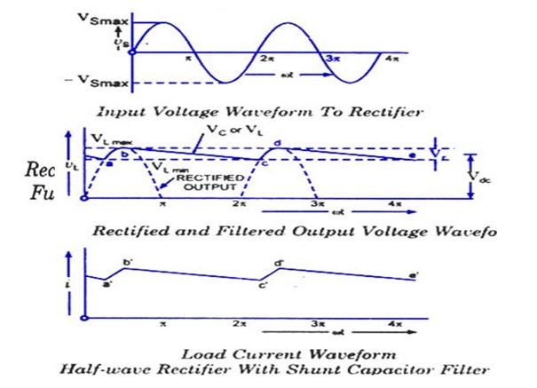
Result:Waveforms of full wave & half wave rectifier is noted down.
| Q.No. | Question | Answers |
| 1 | What is filter? | The device that converts the pulsating output of a rectifier into a steady dc level is known as filter | 2 | Give commonly used filters? | Commonly used filters are Series inductor filter Shunt capacitor filter LC filter П filter | 3 | Define ripple factor? | Ripple factor is defined as the ratio of rms value of the ac component to the dc value of the wave. | 4 | What is dc output voltage given by? | The dc output voltage is given by Vdc =Idc RL | 5 | When we can use inductor small? | We can use inductor filter when RL is consistently small. | 6 | What happens when the filter capacitor value larger? | When the filter capacitor value larger, larger will be the peak current in the rectifying diode. | 7 | What is the value of ripple factor for bridge rectifier? | The value of ripple factor for bridge rectifier is 1.21. | 8 | What is the ripple factor of power supply measured off? | The ripple factor of a power supply is a measure of purity of power output. | 9 | What happens when form factor of filter is higher? | Greater the form factor of a filter, higher its ripple factor. | 10 | What is the value of ripple factor for half wave rectifier? | The value of ripple factor for half wave rectifier is 0.48. |


Get all latest content delivered to your email a few times a month.