To measure the strain using strain gauge.
Strain gauge, weight, LABVIEW software.
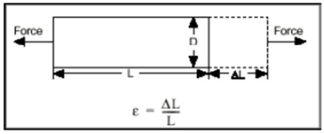
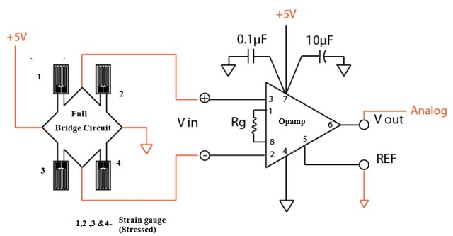
Strain is the amount of deformation of a body due to an applied force. More specifically, strain (e) is defined as the fractional change in length, Strain can be positive (tensile) or negative (compressive). Although dimensionless, strain is sometimes expressed in units such as in./in. or mm/mm. In practice, the magnitude of measured strain is very small. Therefore, strain is often expressed as microstrain (me), which is e x 10-6. When a bar is strained with a uniaxial force, as in Figure 1, a phenomenon known as Poisson Strain causes the girth of the bar, D, to contract in the transverse, or perpendicular, direction. The magnitude of this transverse contraction is a material property indicated by its Poisson's Ratio. The Poisson's Ratio n of a material is defined as the negative ratio of the strain in the transverse direction (perpendicular to the force) to the strain in the axial direction (parallel to the force), or n = eT/e. The most widely used gage is the bonded metallic strain gage. The metallic strain gauge consists of a very fine wire or, more commonly, metallic foil arranged in a grid pattern. The grid pattern maximizes the amount of metallic wire or foil subject to strain in the parallel direction (Figure 2). The cross-sectional area of the grid is minimized to reduce the effect of shear strain and Poisson Strain. The grid is bonded to a thin backing, called the carrier, which is attached directly to the test specimen.

The transformer consists of a single primary P and two secondary windings S1 and S2 wound on a cylindrical former. The secondary windings have equal number of turns and are identically placed on either side. A moveable soft iron core is placed inside the transformer. The displacement to be measured is applied to the arm attached to the soft iron core. In practice the arm is made of highly permeability, nickel iron which is hydrogen annealed. This gives low harmonics low null voltage and high sensitivity. This is slotted longitudinally to reduce eddy current losses. The assembly is placed in stainless steel housing and the end leads provides electrostatic and electromagnetic shielding. The frequency of AC applied to primary windings may be between 50 Hz to 20 kHz. Since the primary winding is excited by an alternating source, it produces an alternating magnetic field which in turn induces alternating current voltage in the two secondary windings. Figure 2 depicts a cross-sectional view of an LVDT. The core causes the magnetic field generated by the primary winding to be coupled to the secondary. When the core is centred perfectly between both secondary and the primary as shown, the voltage induced in each secondary is equal in amplitude and 180 degree out of phase. Thus the LVDT output (for the series-opposed connection shown in this case) is zero because the voltage cancels each other. E0 = Es1-Es2 = 0.

| S.No | Weight in Pan (Grams) | Voltage measured | Display reading | Calculated value |
| 1 | ||||
| 2 | ||||
| 3 | ||||
| 4 | ||||
| 5 | ||||
| 6 | ||||
| 7 | ||||
| 8 | ||||
| 9 | ||||
| 10 |


Get all latest content delivered to your email a few times a month.