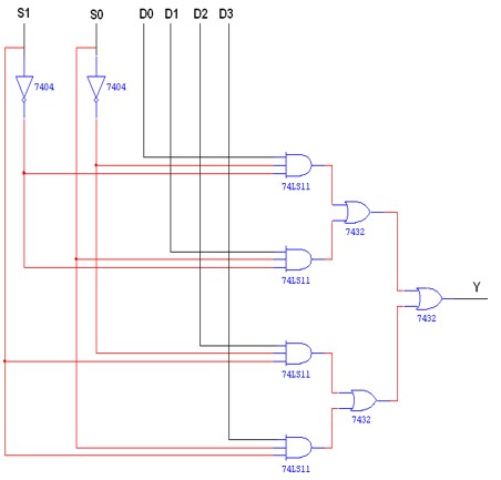
Verification of the truth table of the Multiplexer 74150.
Logic trainer kit, IC- 74150, wires.
A Multiplexer (or a data selector) is a logic circuit that accepts several data inputs and allows only one of them at a time to get through to the output. The selection of the desired data input is controlled by the Select (or Address) Inputs. Multiplexer means transmitting a large number of information units over a smaller number of channels or lines. A digital multiplexer is a combinational circuit that selects binary information from one of many input lines and directs it to a single output line. The selection of a particular input line is controlled by a set of selection lines. Normally there are 2n input line and n selection lines whose bit combination determine which input is selected. Figure below shows the block diagram of a Multiplexer.

In this diagram the inputs and outputs are indicated by means of broad arrows to indicate that there may be one or more lines. Depending upon the digital code applied at the Select inputs, one out of the data sources is selected and transmitted to the single output channel. The Multiplexer becomes enabled when the strobe signal is active Low. The pin out of a 8:1 multiplexer IC 74150 is shown above. The output of this circuit is the inverted input. This is a 16-pin DIP.
| Input/S1/So | Output/Y | |
| 0 | 0 | D0 = D0 S1’ S0’ |
| 0 | 1 | D1 = D1 S1’ S0 |
| 1 | 0 | D2 = D2 S1 S0’ |
| 1 | 1 | D3 = D3 S1 S0 |
| Y | Y = D0 S1’ S0’ +D1 S1’ S0 +D2 S1 S0’ +D3 S1 S0 |

Truth Table
| Input/SO/S1 | Output/Y | |
| 0 | 0 | D0 |
| 0 | 1 | D1 |
| 1 | 0 | D2 |
| 1 | 1 | D3 |
Hence verified the Multiplexer (8:1) operation using IC-74150


Get all latest content delivered to your email a few times a month.