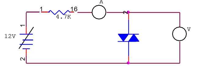
Study of characteristics of DIAC.
Power supply, DIAC Characteristic, Connecting Leads, Ammeter, and Voltmeter.
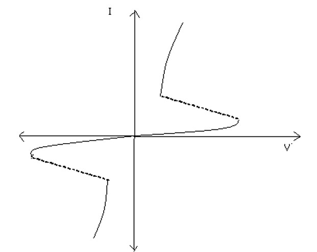
Diac:A Diac is a two terminal & four layer bi-directional semiconductor switching device.‘Di means two (two terminal device) and ‘ac’ means alternating current hence diac is a switch .In fact, it is a device which can conduct in both the directions. Only when the applied voltage is more then its break over voltage. It is similar as if two latches are connected in parallel. During +ve half-Cycle, the right four layer diode conducts heavily. During –ve half-cycle, the left diode conducts heavily only when the supply voltage exceeds the break over voltage of the Diac.

| S. No | DIAC Characteristics/I (mA)/V (Volts) | 1 |
| 2 | ||
| 3 | ||
| 4 | ||
| 5 |
Graph:

Result:The characteristics of DIAC have been plotted.
Precaution:
Q1:Define DIAC?
A1:It is a two electrode bidirectional avalanche diode.
Q2:Define VBO?
A2:The voltage before which DIAC acts as a open switch.
Q3:Write application of Diac?
A3:Heat control circuit.
Q4:Define inter base Resistance?
A4:The total resistance of silicon bar from one end to other end.
Q5:Define valley Point?
A5:Point beyond which if emitter current increases, device enters into saturation region.
Q6:Define peak Point Emitter Current?
A6:Min. current that is required to trigger the device.


Get all latest content delivered to your email a few times a month.