To Study the Series and Shunt Voltage Regulator.
The regulated power supply is a combination of three circuits, the bridge rectifier, the capacitor filter and zener diode voltage Regulator. Basically there are two types of voltage regulators
The series Regulator is placed in series with load and Shunt Regulator is placed in parallel with Load.
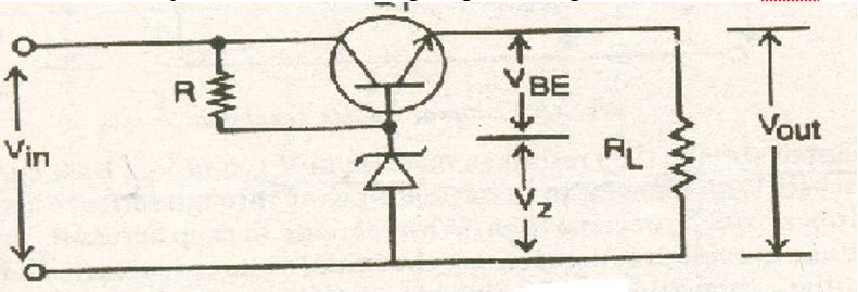
Transistor Series Voltage Regulator A voltage Regulator generally employs some active devices such as zener, or a transistor or both to achieve its objective. A series voltage regular using a transistor and zener diode is as shown,

The circuit is called a series voltage regulator because the load current passes through the series transistor Q1.The main drawback of series regulator is that the pass transistor can be destroyed by excessive load current.
Transistor Shunt Voltage RegulatorAn increase in input voltage results in increase in output voltage and base –Emitter voltage.
Q1:What is the efficiency of CVT
A1:Less than 60%
Q2:The efficiency of voltage stabilizer is between
A2: 70 % to 80%
Q3:What is the output voltage of 7824 IC voltage regulator.
A3:12V
Q4:What is the limitation of zener diode voltage regulator
A4:It has low efficiency for heavy load.
Q5:What are the two types of voltage regulator.
A5:


Get all latest content delivered to your email a few times a month.