Study of Clipping & Clamping circuit.
Power supply, Clipping & Clapping circuit, Connecting leads, CRO.
Clipping: The clippers have the ability to remove signal voltages above or below a specified level & hence change the wave shape of the I/P signal. Most of the clippers employ diodes & are known as diode clippers. Different type of clippers are-
Positive & Negative clipper: A circuit that removes +ve half-cycle of the signal is called +ve clipper. Some times, it is required to remove the –ve half cycle of the I/P signal, the only thing to be done is to reverse the polarity of the diode connected across load, such a clipper is known as a –ve clipper.
Biased clipper: A clipper used to remove a small portion of +ve or –ve half cycle of the signal Voltage is called a biased clipper. A diode is employed in series with a battery of different volts depending upon the requirement.
Combination clipper: In this circuit small portion of +ve as well as small portion of –ve half- Cycle of the signal voltage is removed.
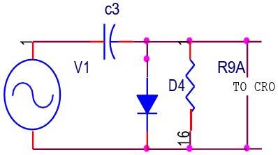
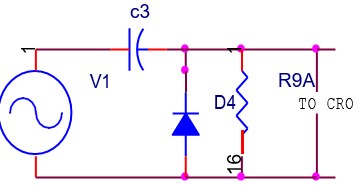
Clamper: A clamping circuit adds d.c component to the signal in such away that it pushes the signal either on the +ve side or on the –ve side. When the circuit pushes the signal on the +ve side then –ve peak of the signal falls on the zero level, this circuit is called a +ve clamper. When the circuit pushes the signal on the –ve side, this is –ve clamper.
Circuit Diagram:
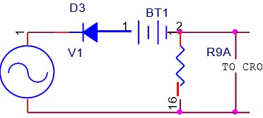
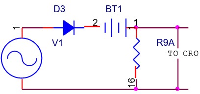
Clipper
Clamper


| Sr.No. | Clipper/I/P(V)/O/P(V) | Clamper/I/P(V)/O/P(V) |
| +VE | -VE |
Precautions:
Result:Verified the circuit diagram of clipper and clamper and waveforms are drawn.
| Q.No. | Question | Answers |
| 1 | What is non-linear wave shaping? | Non linear wave shaping is the process, on applying any wave at input of a non-linear device the shape of the output wave varies non-linearly with the input wave. | 2 | Which are the circuits for non-linear wave shaping? | Clipping circuit & Clamping circuits circuits for non-linear wave shaping. | 3 | What is clipping circuit ? | A wave-shaping circuit which controls the output waveform by removing or clipping a portion of the applied wave is known as clipping circuit. | 4 | According to non-linear devices how clippers can be classified? | According to non-linear devices clippers can be classified as diodes clippers & transistor clippers. | 5 | According to configuration used classify clippers? | According to configuration used classify clippers can be classified as (a)Series diode clipper. (b) Parallel or shunt diode clipper. (c) Combination clippers. | 6 | Classify Clippers level of clippers? | According to level of clipping the clippers may be (a) Positive clippers. (b)Negative clippers (c) Biased clippers (d) Combinational clippers. | 7 | What is positive clipper circuit? | Positive clipper is one which removes the positive half cycles of the input voltage | 8 | What is negative clipper circuit? | Negative clipper is one which removes the negative half cycles of the input voltage | 9 | What is clamping? | A circuit that places either the positive or negative peak of a signal at a desired level is known as Clamping circuit. | 10 | How many types of clampers are there? | There are 2 types of clampers (a) Positive clamper. (b)Negative clamper |



Get all latest content delivered to your email a few times a month.