To get familiar with working knowledge of the following Instruments.
A.Cathode Ray OscilloscopeThe cathode-ray oscilloscope (CRO) is a common laboratory instrument that provides accurate time and amplitude measurements of voltage signals over a wide range of frequencies. Its reliability, stability, and ease of operation make it suitable as a general purpose laboratory instrument. The heart of the CRO is a cathode-ray tube shown schematically in Fig. 1.
-schematic-(b)detail-of-the-deflection-plates.jpg)
The cathode ray is a beam of electrons which are emitted by the heated cathode (negative electrode) and accelerated toward the fluorescent screen. The assembly of the cathode, intensity grid, focus grid, and accelerating anode (positive electrode) is called an electron gun. Its purpose is to generate the electron beam and control its intensity and focus. Between the electron gun and the fluorescent screen are two pair of metal plates - one oriented to provide horizontal deflection of the beam and one pair oriented ot give vertical deflection to the beam. These plates are thus referred to as the horizontal and vertical deflection plates. The combination of these two deflections allows the beam to reach any portion of the fluorescent screen. Wherever the electron beam hits the screen, the phosphor is excited and light is emitted from that point. This conversion of electron energy into light allows us to write with points or lines of light on an otherwise darkened screen.
In the most common use of the oscilloscope the signal to be studied is first amplified and then applied to the vertical (deflection) plates to deflect the beam vertically and at the same time a voltage that increases linearly with time is applied to the horizontal (deflection) plates thus causing the beam to be deflected horizontally at a uniform (constant> rate. The signal applied to the vertical plates is thus displayed on the screen as a function of time. The horizontal axis serves as a uniform time scale.
The linear deflection or sweep of the beam horizontally is accomplished by use of a sweep generator that is incorporated in the oscilloscope circuitry. The voltage output of such a generator is that of a saw tooth wave as shown in Fig. 2. Application of one cycle of this voltage difference, which increases linearly with time, to the horizontal plates causes the beam to be deflected linearly with time across the tube face. When the voltage suddenly falls to zero, as at points (a) (b) (c), etc...., the end of each sweep - the beam flies back to its initial position. The horizontal deflection of the beam is repeated periodically, the frequency of this periodicity is adjustable by external controls.

To obtain steady traces on the tube face, an internal number of cycles of the unknown signal that is applied to the vertical plates must be associated with each cycle of the sweep generator. Thus, with such a matching of synchronization of the two deflections, the pattern on the tube face repeats itself and hence appears to remain stationary. The persistence of vision in the human eye and of the glow of the fluorescent screen aids in producing a stationary pattern. In addition, the electron beam is cut off (blanked) during flyback so that the retrace sweep is not observed
B.The Multimeter StructureThe cathode-ray oscilloscope (CRO) is a common laboratory instrument that provides accurate time and amplitude measurements of voltage signals over a wide range of frequencies. Its reliability, stability, and ease of operation make it suitable as a general purpose laboratory instrument. The heart of the CRO is a cathode-ray tube shown schematically in Fig. 1.

A multimeter is used to make various electrical measurements, such as AC and DC voltage, AC and DC current, and resistance. It is called a multimeter because it combines the functions of a voltmeter, ammeter, and ohmmeter. Multimeters may also have other functions, such as diode and continuity tests. The descriptions and pictures that follow are specific to the Fluke 73 Series III Multimeter, but other multimeters are similar.
Important note: The most common mistake when using a multimeter is not switching the test leads when switching between current sensing and any other type of sensing (voltage, resistance). It is critical that the test leads be in the proper jacks for the measurement you are making.
Safety Information
C. Function GeneratorA function generator is a device that can produce various patterns of voltage at a variety of frequencies and amplitudes. It is used to test the response of circuits to common input signals. The electrical leads from the device are attached to the ground and signal input terminals of the device under test.
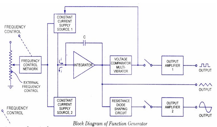
Features and controls
How to use a function generator?
Conclusions
D.Regulated Power Supply
Types of Power SupplyThere are many types of power supply. Most are designed to convert high voltage AC mains electricity to a suitable low voltage supply for electronics circuits and other devices. A power supply can by broken down into a series of blocks, each of which performs a particular function.
For example a 5V regulated supply:

Each of the blocks is described in more detail below:
E.Active, Passive Components An electronic component is a basic electronic element and may be available in a discrete form (a discrete device or discrete component) having two or more electrical terminals (or leads). These are intended to be connected together, usually by soldering to a printed circuit board, in order to create an electronic circuit(a discrete circuit) with a particular function (for example an amplifier, radio receiver, or oscillator). Basic electronic components may be packaged discretely, as arrays or networks of like components, or integrated inside of packages such as semiconductor integrated circuits, hybrid integrated circuits, or thick film devices.
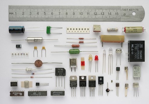
A component may be classified as passive or active. The strict physics definition treats passive components as ones that cannot supply energy themselves, whereas a battery would be seen as an active component since it truly acts as a source of energy.
Passive components are ones which cannot introduce net energy into the circuit they are connected to. They also cannot rely on a source of power except for what is available from the (AC) circuit they are connected to. As a consequence they are unable to amplify (increase the power of a signal), although they may well increase a voltage or current such as is done by a transformer or resonant circuit. Among passive components are familiar two-terminal components such as resistors, capacitors, inductors, and transformers.
Active components rely on a source of energy (usually from the DC circuit, which we have chosen to ignore) and are usually able to inject power into a circuit although this is not part of the definition[1]. This includes amplifying components such as transistors, triode vacuum tubes(valves), and tunnel diodes.
Passive components can be further divided into lossless and lossy components:
Lossless components do not have a net power flow into or out of the component. This would include ideal capacitors, inductors, transformers, and the (theoretical) gyrator.
Lossy or dissipative components do not have that property and generally absorb power from the external circuit over time. The prototypical example is the resistor. In practice all non- ideal passive components are at least a little lossy, but these are typically modeled in circuit analysis as consisting of an ideal lossless component with an attached resistor to account for the loss.
Most passive components with more than two terminals can be described in terms of two-port parameters satisfying the principle of reciprocity, although there are some rare exceptions[2]. In contrast, active components (which have more than two terminals) generally lack that property. Note that these distinctions only apply to components listed below which would be modeled as elements within circuit analysis. Practical items which act as transducers or have other connections to the outside world such as switches, cannot be subject to this form of classification since they defy the view of the electronic circuit as a closed system.
Bread BoardA breadboard is used to build and test circuits quickly before finalizing any circuit design. The breadboard has many holes into which circuit components like ICs and resistors can be inserted. A typical breadboard is shown below:
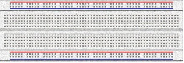
The bread board has strips of metal which run underneath the board and connect the holes on the top of the board. The metal strips are laid out as shown below. Note that the top and bottom rows of holes are connected horizontally while the remaining holes are connected vertically.
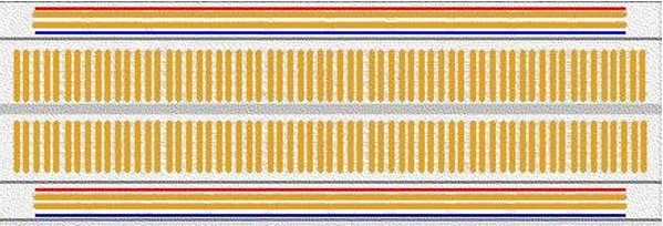
To use the bread board, the legs of components are placed in the holes. Each set of holes connected by a metal strip underneath forms a node. A node is a point in a circuit where two components are connected. Connections between different components are formed by putting their legs in a common node. The long top and bottom row of holes are usually used for power supply connections. The rest of the circuit is built by placing components and connecting them together with jumper wires. ICs are placed in the middle of the board so that half of the legs are on one side of the middle line and half on the other.
A completed circuit might look like the following.
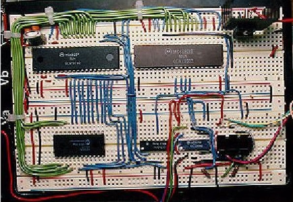
Bread boarding tips:It is important to breadboard a circuit neatly and systematically, so that one can debug it and get it running easily and quickly. It also helps when someone else needs to understand and inspect the circuit. Here are some tips:
Quiz:
Q:What are the uses of CRO?
A:Calibrate an oscillator, Compare two frequency generators, Phase shift determination b/w V and I in any CRT circuit, study Beats phenomenon, study Lisajjous figures
Q:For what electron gun assembly is provided in a CRT?
A:To provide a narrow& sharply focused electron beam
Q:What is meant by deflection sensitivity of a CRO?
A:Vertical deflection of the beam on the screen per unit deflecting voltage
Q:What is the deflection factor of a CRO?
A:Reciprocal of deflection sensitivity.
Q:What is a CRO?
A:Electronic device is an electronic device with a CRT as its main component & other associated circuits consisting of a power supply unit, a saw-tooth wave generator, horizontal & vertical amplifiers.
Q:What is a function generator?
A:It is a signal source that has capability of producing different types of waveforms & frequencies
Q:How the frequency of a function generator is controlled?
A:By varying the magnitude of current that drives the integrator
Q:What is a regulated power supply?
A:An electronic circuit which provide constant DC voltage of predetermined value across load terminals, which is independent of variations in load current.
Q:What are the basic components of a regulated power supply?
A:A transformer, rectifier circuit, filter, voltage regulator
Q:What is the need of voltage regulators?
A:To keep output voltage constant against variations in load current & in AC mains voltage.
Q:what is breadboard?
A:A breadboard is used to build and test circuits quickly before finalizing any circuit design. The breadboard has many holes into which circuit components like ICs and resistors can be inserted.
Q:Q. What is the difference between active and passive components?
A:Passive elements don't require power from the supply to produce its effect on a signal. They derive the power of the input signal to perform its action. for example, a resistor doesn't require a separate supply to provide its action of resistance in a circuit. Where as in active elements there should be a power source for its working. They require a supply for there working. For instance, transistors - Only after biasing the transistor in required region of operation, its characteristics are applied on the signal. i.e, for amplification, transistor require a source from where it can work in.


Get all latest content delivered to your email a few times a month.